Frequency Converter SD4S
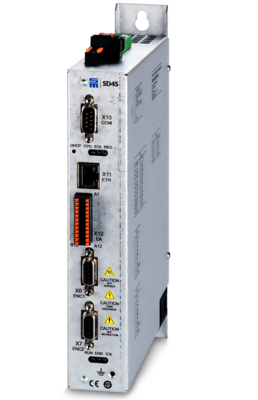
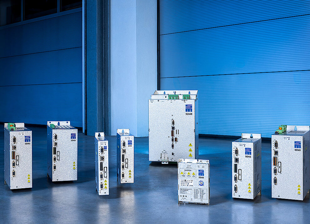
The SD4S series is the successor to the proven SD2S variants. The SD4S devices are designed for stationary use in control cabinets of machine tools, turbo compressors and turbo blowers.
Highlights
Better Performance and New Control Functions
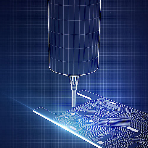
The first available unit type is designed for small high-speed spindles or motors in the power range from a few hundred watts to 1 kW. Application areas are e.g. dental milling machines or machines for super finishing as those required in watchmaking. Since small spindles do not come with a sufficient insulation resistance in the motors, SD4S now features a galvanic isolation of the thermal contact.
An absolute novelty is the design width of 40 mm only. Particularly in applications with many axes and a low performance, the demand for highly compact drive systems is great. Thus, the construction volume has been further reduced. The parameterization is realized via a default Ethernet interface that replaces the USB interface, which in industrial environments is prone to failure.
Moreover, SD4S comes with programmable digital measuring system interfaces such as Biss-C, EnDat2.2 and TTL. Via a Webserver, technicians can display device information without the need of additional parameterization software. Thanks to the real-time clock, a time synchronization of an incident is possible: Users can figure out whether a failure has been caused for example by a thunderstorm.
The optimized performance, higher speeds as well as the lower motor heating without sine-wave filter are substantial advantages of SD4S.
SD4S - Always the Perfect Drive Function for Your Application
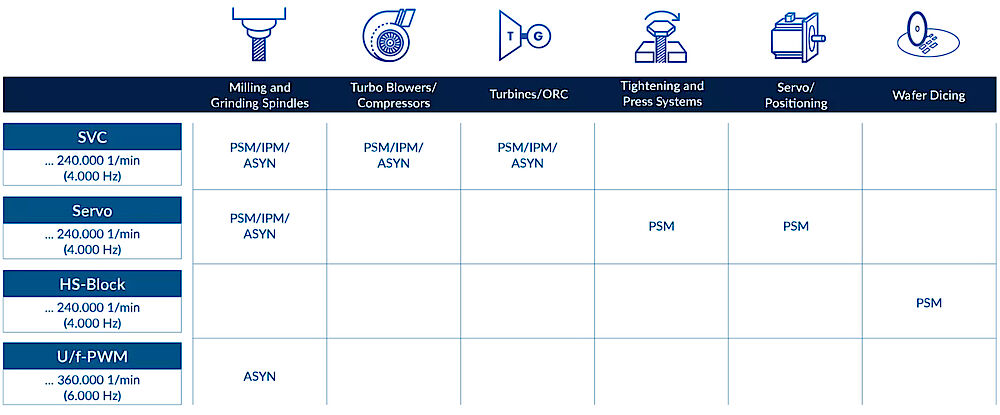
PSM: (Permanently excited synchronous motor)
IPM (Interior Synchronous Permanent Magnet Motor)
ASYN: (Asynchronous motor)
SVC: (Sensorless vector control)
Servo: (Servo mode with encoder feedback)
V/f-PWM: (Sensorless V/f characteristic control based on pulse width modulation)
HS-Block: (Block control with Hall elements)
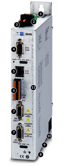
The Interfaces of Frequency Converter SD4S
- Supply voltage / external ballast resistor
- 24 VDC logic power supply
- Safety integrated „STO“: Restart lock to meet category 4/PL e according to EN ISO 13849 1:2015 and EN 61508:2010 SIL3
- RS232/485, CAN, CANopen, Modbus RTU
- Ethernet 100 MBit, parameterization, diagnosis and operation, Modbus TCP
- I/O interface: 1 digital relay output, 4 digital outputs, 8 digital inputs
- Digital motor encoder interface (BiSS C, EnDat 2.2, TTL, Hall sensor)
- Optional: PROFINET IO, EtherCAT, POWERLINK
- Galvanically isolated thermal contact
- Motor connection
- Analog motor encoder interface (resolver, linear Hall, SinCos 1 Vpp)
Drive Functions and Safety Functions
Software for Initial Operation and Parameterization: drivemaster4
The parameterization, simulation and diagnostic software drivemaster4 enables the user to commission drive systems easily and quickly. With the integrated simulation tool Motor Analyzer, the user can already prove at the time of system design that the desired system characteristics in terms of operating points and harmonics can be realized. The basis for this is suitable electrical motor data.
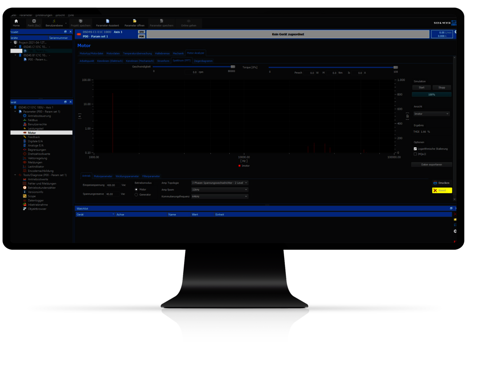
Simulation:
- Electrical operating points
- Influence of PWM frequency/converter topology
- FFT analysis including THDi/THDu calculation
- Export of simulation data
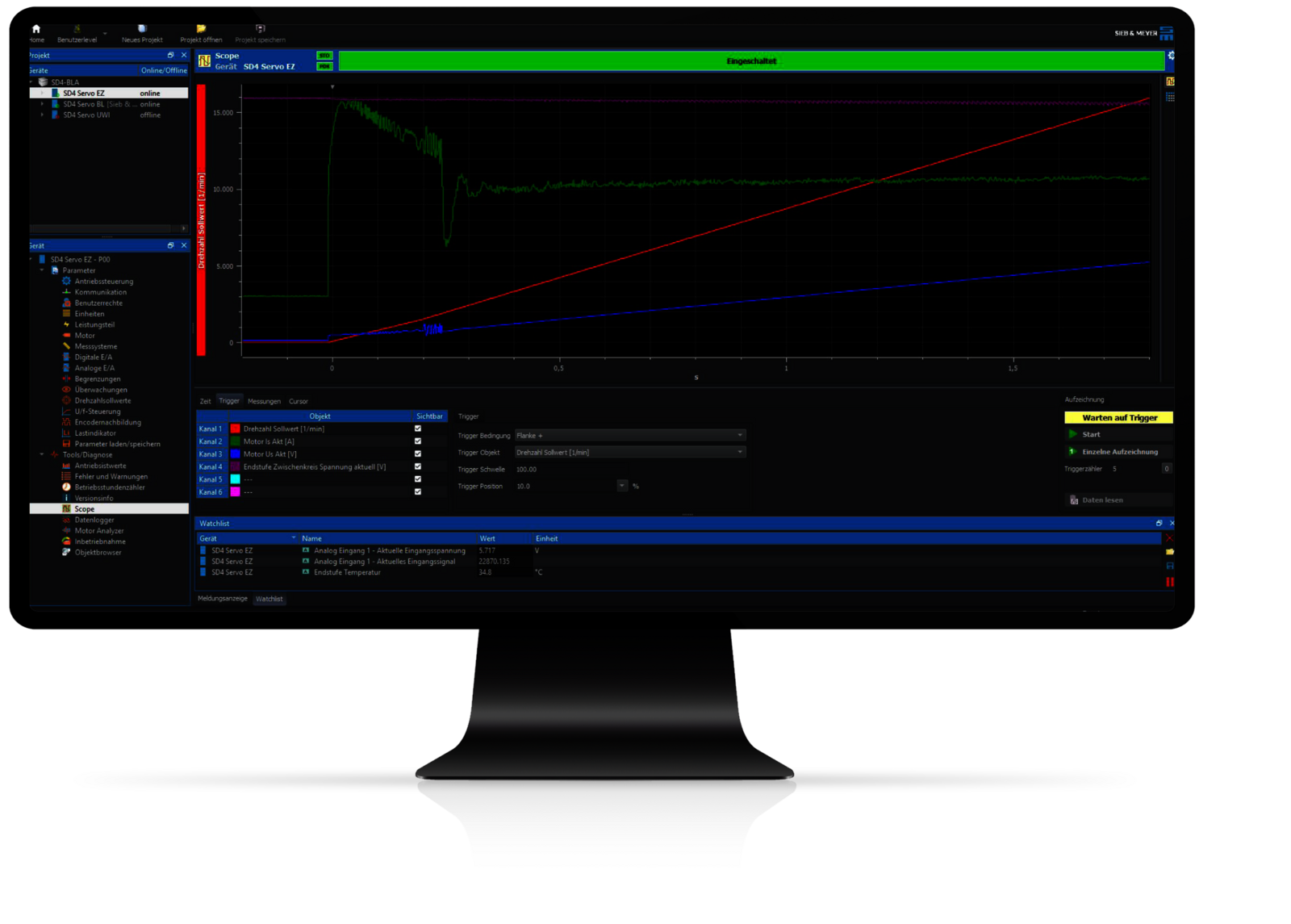
Start-up:
- Parameterization of the motor data/interfaces
- Optimization by means of oscilloscope
- Commissioning tool
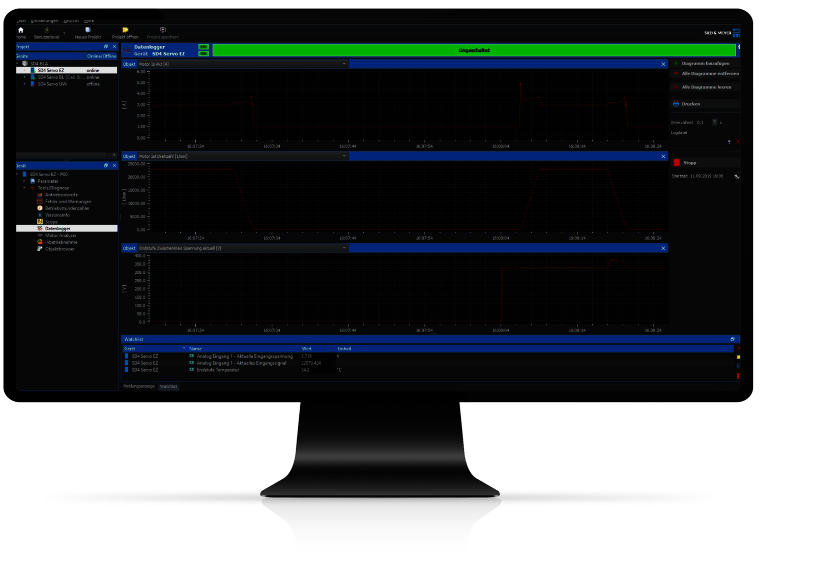
Monitoring:
- Data logger
- Real-time clock
- Error memory
- Operating hours counter
Technical Specifications of Frequency Converter SD4S
Voltage Class 50 VAC
Input Voltage Range 45..80 VAC
| Device type | Mains voltage | Output power[kW] | Apparent output power [kVA] | Output current [A] | Peak output current [A] | H x W x D (mm) | Weight | Cooling |
|---|---|---|---|---|---|---|---|---|
| 0SD4SB1D1Axxxx | 1 x 50 VAC | 0.3 kW | 0.7 kVA@16 kHz | 8 A@16 kHz | 14 A | 247 x 43 x 186 | 1.23 kg | Air |
| 0SD4SC1E1Axxxx | 1 x 50 VAC | 0.6 kW | 1.2 kVA@16 kHz | 14 A@16 kHz | 28 A | 247 x 63 x 186 | 2.15 kg | Air |
Voltage Class 230 VAC
Input Voltage Range 99..253 VAC
| Device type | Mains voltage | Output power[kW] | Apparent output power [kVA] | Output current [A] | Peak output current [A] | H x W x D (mm) | Weight | Cooling |
|---|---|---|---|---|---|---|---|---|
| 0SD4SB1D1Cxxxx | 1 x 230 VAC | 0.8 kW | 1.6 kVA@16 kHz | 4 A@16 kHz | 14 A | 247 x 43 x 186 | 1.23 kg | Air |
| 0SD4SC1E1Cxxxx | 1 x 230 VAC | 1.6 kW | 3.2 kVA@16 kHz | 8 A@16 kHz | 28 A | 247 x 63 x 186 | 2.15 kg | Air |
| 0SD4SD1E1Cxxxx | 1 x 230 VAC | 2.4 kW | 6.4 kVA@16 kHz | 16 A@16 kHz | 28 A | 247 x 83 x 186 | 2.4 kg | Air |
Voltage Class 400 VAC
Input Voltage Range 180..528 VAC
| Device type | Mains voltage | Output power [kW] | Apparent output power [kVA] | Output current [A] | Peak output current [A] | H x W x D (mm) | Weight | Cooling |
|---|---|---|---|---|---|---|---|---|
| 0SD4SD1B1Fxxxx | 3 x 400 VAC | 4 kW | 5.5 kVA@16 kHz | 8 A@16 kHz | 20 A | 247 x 83 x 186 | 2.46 kg | Air |
| 0SD4SD1F1Fxxxx | 3 x 400 VAC | 6 kW | 8.3 kVA@16 kHz | 12 A@16 kHz | 24 A | 247 x 83 x 186 | 2.46 kg | Air |
| 0SD4SE1I1Fxxxx | 3 x 400 VAC | 10 kW | 13.9 kVA@16 kHz | 20 A@16 kHz | 56 A | 278 x 93 x 225 | 4.8 kg | Air |
| 0SD4SF1I1Fxxxx | 3 x 400 VAC | 15 kW | 20.8 kVA@16 kHz | 30 A@16 kHz | 56 A | 278 x 118 x 225 | 5.6 kg | Air |
| 0SD4SH1M1Fxxxx* | 3 x 400 VAC | 24 kW | 33 kVA@16 kHz | 48 A@16 kHz | 96 A | 400 x 131 x 125 | approx. 10 kg | Air |
| 0SD4SH1N1Fxxxx* | 3 x400 VAC | 32 kW | 44 kVA@16 kHz | 64 A@16kHz | 96 A | 400 x 131 x 125 | approx. 10.5 kg | Air |
| 0SD4SK1N1Fxxxx* | 3 x 400 VAC | 48 kW | 66 kVA@16 kHz | 96 A@16 kHz | 120 A | 440 x 176 x 125 | approx. 15 kg | Air |
* in realization
News
SIEB & MEYER AG Doubles Sales in 2025

Drive Controller SD4S by SIEB & MEYER
A Drive Controller for All Purposes
Feel free to contact us
![[Translate to Englisch:] Frequenzumrichter SD4S](/fileadmin/_processed_/7/3/csm_Header_SD24S_498bc68d08.png)
Frequency Converter SD4S
The product version SD4S - S for Stand-alone - is the first device of the new product series SD4x. The SD4S devices are designed for stationary use in control cabinets of machine tools, turbo compressors and turbo blowers.
Highlights
PWM Frequencies up to 32 kHz
- Function: The SD4S provides PWM frequencies up to 32 kHz and commutation frequencies up to 64 kHz.
- Advantage: Higher rotating field frequencies up to 6,000 Hz and lower harmonic frequency components.
- Benefit: Realization of higher pole motor designs and lower motor losses.
Motor Analyzer
- Function: Simulation of the operating points and FFT analysis with THDi and THDu calculation.
- Advantage: Analysis of system performance already at the start of development.
- Benefit: Reduction of development time, costs and risk as well as optimization of the overall system.
Galvanically Isolated Thermal Contact Input
- Function: The input for the thermal contact is galvanically isolated from the logic and main voltage.
- Advantage: Safe operation even in case of an insulation problem of the thermal contact in the motor.
- Benefit: Protection of the inverter in the event of a fault and higher system availability.
Better Performance and New Control Functions
The first available unit type is designed for small high-speed spindles or motors in the power range from a few hundred watts to 1 kW. Application areas are e.g. dental milling machines or machines for super finishing as those required in watchmaking. Since small spindles do not come with a sufficient insulation resistance in the motors, SD4S now features a galvanic isolation of the thermal contact.
An absolute novelty is the design width of 40 mm only. Particularly in applications with many axes and a low performance, the demand for highly compact drive systems is great. Thus, the construction volume has been further reduced. The parameterization is realized via a default Ethernet interface that replaces the USB interface, which in industrial environments is prone to failure.
Moreover, SD4S comes with programmable digital measuring system interfaces such as Biss-C, EnDat2.2 and TTL. Via a Webserver, technicians can display device information without the need of additional parameterization software. Thanks to the real-time clock, a time synchronization of an incident is possible: Users can figure out whether a failure has been caused for example by a thunderstorm.
The optimized performance, higher speeds as well as the lower motor heating without sine-wave filter are substantial advantages of SD4S.
SD4S - Always the Perfect Drive Function for Your Application
PSM: (Permanently excited synchronous motor)
IPM (Interior Synchronous Permanent Magnet Motor)
ASYN: (Asynchronous motor)
SVC: (Sensorless vector control)
Servo: (Servo mode with encoder feedback)
V/f-PWM: (Sensorless V/f characteristic control based on pulse width modulation)
HS-Block: (Block control with Hall elements)

The Interfaces of Frequency Converter SD4S
![[Translate to Englisch:] Frequenzumrichter SD4S](/fileadmin/_processed_/f/0/csm_2500x2500_Schnittstellen_Frequenzumrichter-SD4S_01_59762629f6.png)
- Supply voltage / external ballast resistor
- 24 VDC logic power supply
- Safety integrated „STO“: Restart lock to meet category 4/PL e according to EN ISO 13849 1:2015 and EN 61508:2010 SIL3
- RS232/485, CAN, CANopen, Modbus RTU
- Ethernet 100 MBit, parameterization, diagnosis and operation, Modbus TCP
- Digital inputs and outputs
- Digital motor encoder interface (BiSS C, EnDat 2.2, TTL)
- Optional: EtherCAT, Profinet, Powerlink
- Galvanically isolated thermal contact
- Motor connection
- Analog motor encoder interface (Resolver, SinCos 1 Vpp)
Drive Functions and Safety Functions
Software for Initial Operation and Parameterization: drivemaster4
The parameterization, simulation and diagnostic software drivemaster4 enables the user to commission drive systems easily and quickly. With the integrated simulation tool Motor Analyzer, the user can already prove at the time of system design that the desired system characteristics in terms of operating points and harmonics can be realized. The basis for this is suitable electrical motor data.
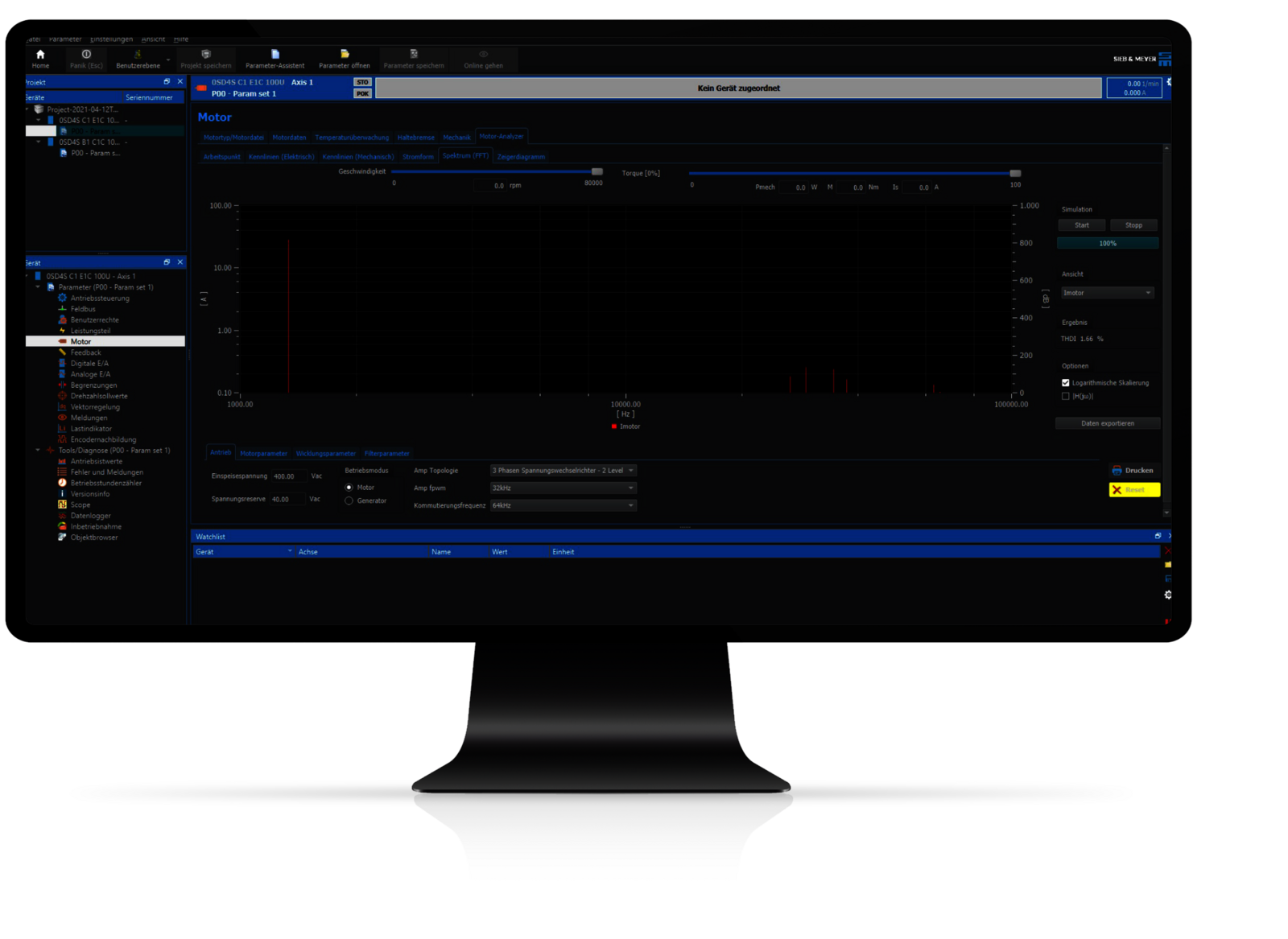
Simulation:
• Electrical operating points
• Influence of PWM frequency/converter topology
• FFT analysis including THDi/THDu calculation
• Export of simulation data
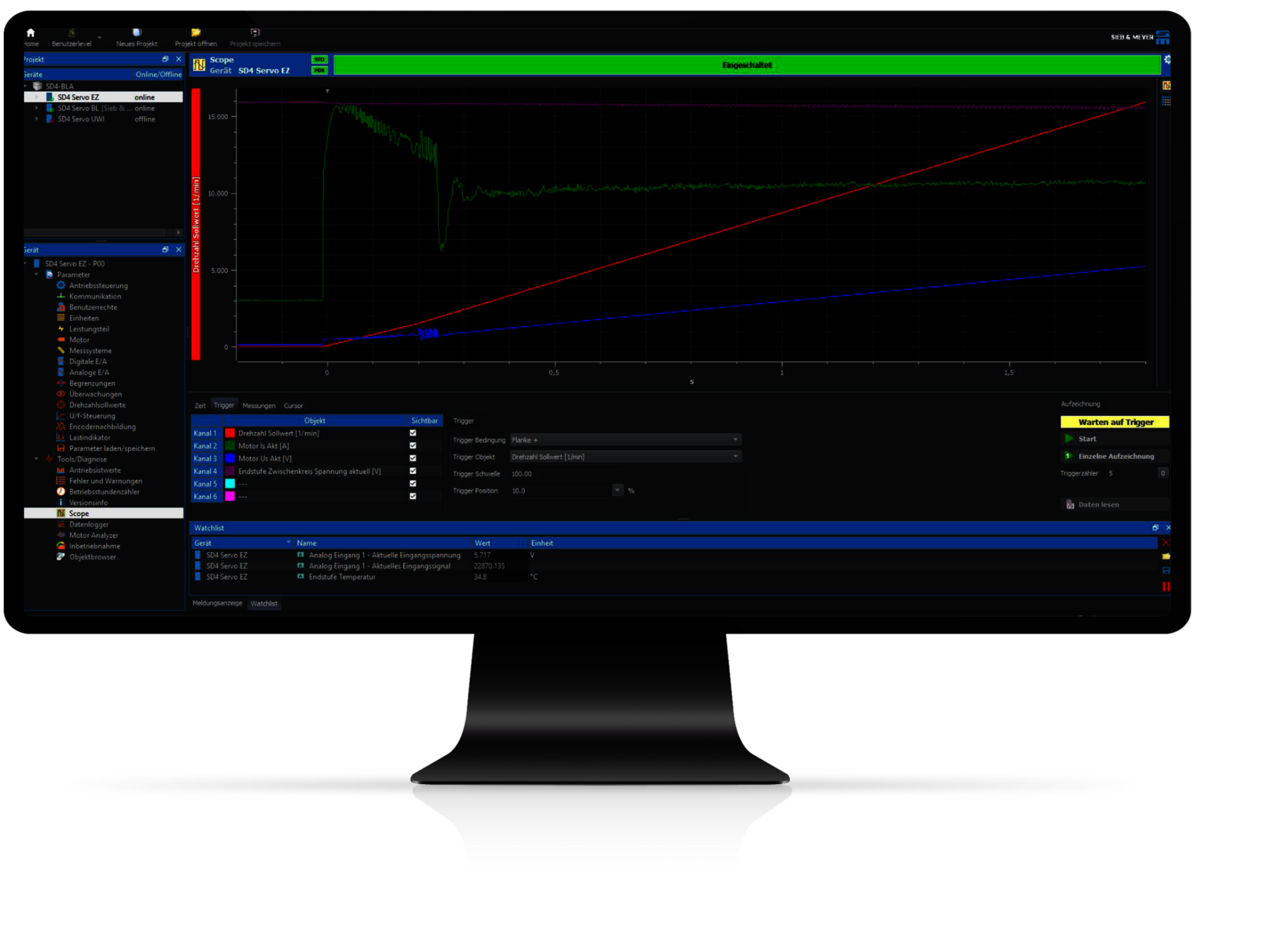
Start-up:
• Parameterization of the motor data/interfaces
• Optimization by means of oscilloscope
• Commissioning tool
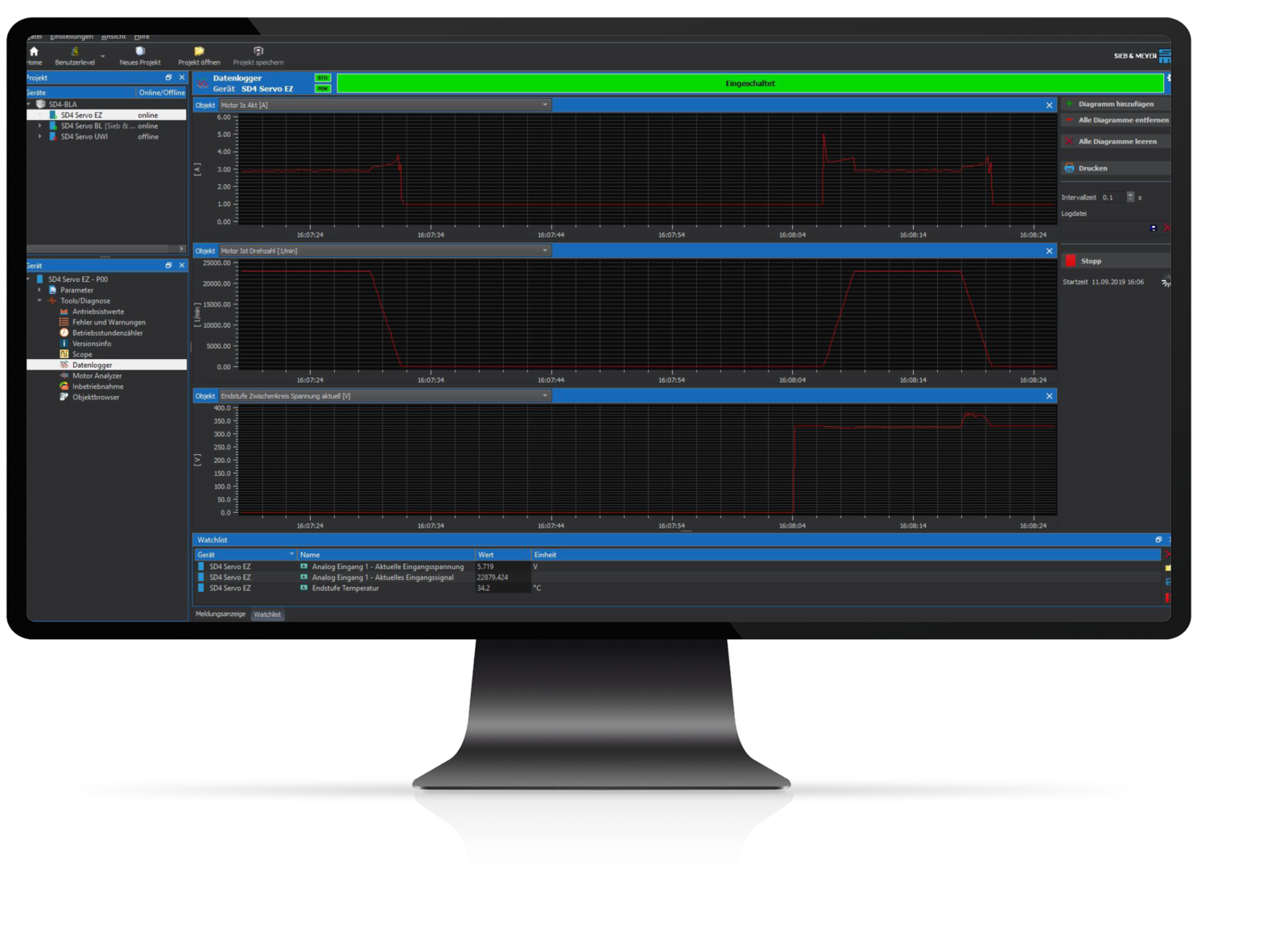
Monitoring:
• Data logger
• Real-time clock
• Error memory
• Operating hours counter
Technical Specifications of Frequency Converter SD4S
Voltage Class 50 V:
| Device type | Mains voltage | Output power[kW] | Apparent output power [kVA] | Output current [A] | Peak output current [A] | H x W x D (mm) | Weight | Cooling |
|---|---|---|---|---|---|---|---|---|
| 0SD4SB1D1Axxxx | 1 x 50 VAC | 0.3 kW | 0.7 kVA@16 kHz | 8 A@16 kHz | 14 A | 247 x 43 x 186 | 1.23 kg | Air |
| 0SD4SC1E1Axxxx | 1 x 50 VAC | 0.6 kW | 1.2 kVA@16 kHz | 14 A@16 kHz | 28 A | 247 x 63 x 186 | 2.15 kg | Air |
Voltage Class 230 V:
| Device type | Mains voltage | Output power[kW] | Apparent output power [kVA] | Output current [A] | Peak output current [A] | H x W x D (mm) | Weight | Cooling |
|---|---|---|---|---|---|---|---|---|
| 0SD4SB1D1Cxxxx | 1 x 230 VAC | 0.8 kW | 1.6 kVA@16 kHz | 4 A@16 kHz | 14 A | 247 x 43 x 186 | 1.23 kg | Air |
| 0SD4SC1E1Cxxxx | 1 x 230 VAC | 1.6 kW | 3.2 kVA@16 kHz | 8 A@16 kHz | 28 A | 247 x 63 x 186 | 2.15 kg | Air |
| 0SD4SD1E1Cxxxx | 1 x 230 VAC | 2.4 kW | 6.4 kVA@16 kHz | 16 A@16 kHz | 28 A | 247 x 83 x 186 | 2.4 kg | Air |
Voltage Class 400 V:
| Device type | Mains voltage | Output power [kW] | Apparent output power [kVA] | Output current [A] | Peak output current [A] | H x W x D (mm) | Weight | Cooling |
|---|---|---|---|---|---|---|---|---|
| 0SD4SD1B1Fxxxx | 3 x 400 VAC | 4 kW | 5.5 kVA@16 kHz | 8 A@16 kHz | 20 A | 247 x 83 x 186 | 2.46 kg | Air |
| 0SD4SD1F1Fxxxx | 3 x 400 VAC | 6 kW | 8.3 kVA@16 kHz | 12 A@16 kHz | 24 A | 247 x 83 x 186 | 2.46 kg | Air |
| 0SD4SE1I1Fxxxx | 3 x 400 VAC | 10 kW | 13.9 kVA@16 kHz | 20 A@16 kHz | 56 A | 278 x 93 x 225 | 4.8 kg | Air |
| 0SD4SF1I1Fxxxx | 3 x 400 VAC | 15 kW | 20.8 kVA@16 kHz | 30 A@16 kHz | 56 A | 278 x 118 x 225 | 5.6 kg | Air |
| 0SD4SH1M1Fxxxx* | 3 x 400 VAC | 24 kW | 33 kVA@16 kHz | 48 A@16 kHz | 96 A | 400 x 131 x 125 | approx. 10 kg | Air |
| 0SD4SH1N1Fxxxx* | 3 x400 VAC | 32 kW | 44 kVA@16 kHz | 64 A@16kHz | 96 A | 400 x 131 x 125 | approx. 10.5 kg | Air |
| 0SD4SK1N1Fxxxx* | 3 x 400 VAC | 48 kW | 66 kVA@16 kHz | 96 A@16 kHz | 120 A | 440 x 176 x 125 | approx. 15 kg | Air |
* in realization
Applications
About Sieb & Meyer
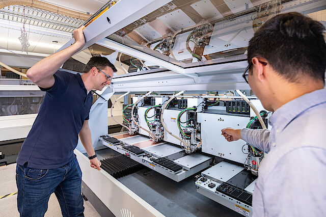
SIEB & MEYER AG - Drive and control solutions of the latest generation
SIEB & MEYER was founded in 1962 and is a successful company in the field of industrial electronics. With around 300 employees worldwide today, we develop and manufacture control technology and drive electronics. Our core technologies include controllers for mechanical engineering and automation technology, servo amplifiers for a wide range of drives and frequency converters for high-speed motors and generators.
Contact
SIEB & MEYER AG
Auf dem Schmaarkamp 21
D-21339 Lüneburg
Phone: +49 4131 203 0
Fax: +49 4131-203 2000
You can find all sales contacts at: www.sieb-meyer.com/contact/sales
You can find all agencies and partners at: www.sieb-meyer.com/contact/offices-and-sales-partners
