Frequency Converter FC2
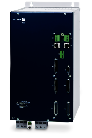
The FC2 offers the possibility to drive up to eight asynchronous high-speed spindles at the same time. The device topology with the controlled DC link and the PAM modulation allows to drive asynchronous motors up to a rotating field frequency of 8,333 Hz (500,000 rpm) without encoder and without motor chokes. The output voltage of max. 3 x 230 VAC is optimized for the high-speed spindles used in PCB drilling and milling. By means of parameter switching/spindle selection, the converter parameters are automatically adjusted depending on the selected spindles. In order to reduce the number of external components, the FC2 offers the possibility of evaluating up to eight speed and temperature sensors.
Highlights
Device Topology


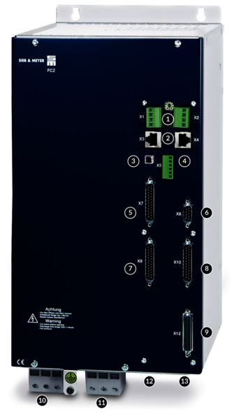
The Interfaces of Frequency Converter FC2
- 24 VDC logic supply
- RS232- /485- / CAN Bus interface
- USB connection, parameterization, diagnosis
- Safety Intergrated "STO": Restart lock to meet category 4/PL e according to EN ISO 13849-1:2015 and EN 61508:2010 SIL
- Spindle selection - inputs
- 2 analog reference value interfaces: +/-10 V; 2 analog outputs: 0 - 10 V
- Spindle selection - ouputs
- 5 digital inputs and 6 digital outputs
- Motor encoder interface: 8 x magnetoresistive sensor, motor temperature sensor
- Power supply
- Motor connection
- EtherCAT (CoE)
- SERVOLINK 4
Drive functions and safety functions
Software for initial operation and parameterization: drivemaster2
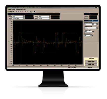
The oscilloscope function allows optimization of the motors in the machine via the drive-setup-tool without additional measuring equipment.
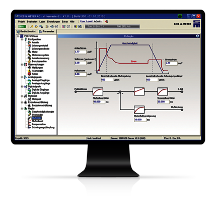
The clear design of the software allows intuitive parameterization via graphics and block diagrams. The „Parameter-Wizard“ guides the user step-by-step through the system configuration and allows intuitive setup of the device via help messages and comments.
Technical Specifications of Frequency Converter FC2
| Device type | Rated power1 | Rated current | Peak current/time | Max. output voltage1 | HxWxD (mm) | Weight | Cooling |
|---|---|---|---|---|---|---|---|
| Compact devices - 3 x 200...480 VAC mains voltage | |||||||
| 0219x100IF | 13 kVA | 33.6 Arms | 50.4 Arms/15 s | 3 x 220 VAC | 389 x 208 x 226 | 12.8 kg | Air |
X = 1: CAN bus
X = 2: EtherCAT and CAN Bus
1) Rated power and max. output voltage for mains voltage/supply voltage (in italic)
Feel free to contact us
![[Translate to Englisch:] Frequenzumrichter FC2](/fileadmin/_processed_/5/6/csm_Header_FC2_55a9cf9653.png)
Frequency Converter FC2
The FC2 offers the possibility to drive up to eight asynchronous high-speed spindles at the same time. The device topology with the controlled DC link and the PAM modulation allows to drive asynchronous motors up to a rotating field frequency of 8,333 Hz (500,000 rpm) without encoder and without motor chokes. The output voltage of max. 3 x 230 VAC is optimized for the high-speed spindles used in PCB drilling and milling. By means of parameter switching/spindle selection, the converter parameters are automatically adjusted depending on the selected spindles. In order to reduce the number of external components, the FC2 offers the possibility of evaluating up to eight speed and temperature sensors.
Highlights
Output Frequencies up to 8,333 Hz
- Function: Established PAM technology with optimized dynamic characteristics, efficiency and flexibility.
- Advantage: Virtually no speed limitation combined with optimized control dynamics and excellent system efficiency.
- Benefit: Low initial costs, possibility to access new applications.
Multi-spindle operation of up to eight asynchronous spindles
- Function: Parallel operation of up to 8 asynchronous spindles and evaluation of speed encoders and temperature sensors.
- Advantage: Only one frequency converter needed and no external components for evaluation.
- Benefit: Cost and space savings, easy parameterization.
No Need of Motor Chokes or LC-Filters
- Function: The PAM technology allows smallest switching frequencies and reduces the isolation stress of the motor as well as interferences (EMC) significantly.
- Advantage: Additional filter elements or motor chokes are not required.
- Benefit: Low system costs, easy initial operation.
Device Topology


The Interfaces of Frequency Converter FC2
![[Translate to Englisch:] Frequenzumrichter FC2](/fileadmin/_processed_/8/3/csm_2500x2500_Schnittstellen_FC2_c667571545.png)
- 24 VDC logic supply
- RS232- /485- / CAN Bus interface
- USB connection, parameterization, diagnosis
- Safety Intergrated "STO": Restart lock to meet category 4/PL e according to EN ISO 13849-1:2015 and EN 61508:2010 SIL
- Spindle selection - inputs
- 2 analog reference value interfaces: +/-10 V; 2 analog outputs: 0 - 10 V
- Spindle selection - ouputs
- 5 digital inputs and 6 digital outputs
- Motor encoder interface: 8 x magnetoresistive sensor, motor temperature sensor
- Power supply
- Motor connection
- EtherCAT (CoE)
- SERVOLINK 4
Drive functions and safety functions
Software for initial operation and parameterization: drivemaster2

The oscilloscope function allows optimization of the motors in the machine via the drive-setup-tool without additional measuring equipment.

The clear design of the software allows intuitive parameterization via graphics and block diagrams. The „Parameter-Wizard“ guides the user step-by-step through the system configuration and allows intuitive setup of the device via help messages and comments.
Technical Specifications of Frequency Converter FC2
| Device type | Rated power1 | Rated current | Peak current/time | Max. output voltage1 | HxWxD (mm) | Weight | Cooling |
|---|---|---|---|---|---|---|---|
| Compact devices - 3 x 200...480 VAC mains voltage | |||||||
| 0219x100IF | 13 kVA | 33.6 Arms | 50.4 Arms/15 s | 3 x 220 VAC | 389 x 208 x 226 | 12.8 kg | Air |
X = 1: CAN bus
X = 2: EtherCAT and CAN Bus
1) Rated power and max. output voltage for mains voltage/supply voltage (in italic)
Applications
About Sieb & Meyer
SIEB & MEYER AG - Drive and control solutions of the latest generation
SIEB & MEYER was founded in 1962 and is a successful company in the field of industrial electronics. With around 300 employees worldwide today, we develop and manufacture control technology and drive electronics. Our core technologies include controllers for mechanical engineering and automation technology, servo amplifiers for a wide range of drives and frequency converters for high-speed motors and generators.
Contact
SIEB & MEYER AG
Auf dem Schmaarkamp 21
D-21339 Lüneburg
Phone: +49 4131 203 0
Fax: +49 4131-203 2000
You can find all sales contacts at: www.sieb-meyer.com/contact/sales
You can find all agencies and partners at: www.sieb-meyer.com/contact/offices-and-sales-partners
